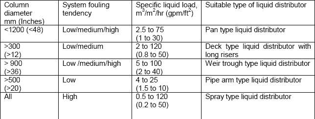
An orifice typepan liquid distributor the most conventional type allows gas to pass the plate through risers while liquid flows through openings in the floorThe standard design has a turndown ratio of 21 and the pressure drop in water is typically 02 06. An overall maldistribution quality is determined as a characteristic value for evaluation.

Column Internals Explained Part 2 Separation Technologies
7 Model 186 Trough Distributor Model 196 Packed Trough Very Low Flow Distributor n Metering device.

. Settling of the larger droplets downstream of the coalescer. Separate liquid collector n Standard features 21 turndown ratio. Trough wall orifices with guide tubes n 2Liquid rates.
Liquid distributor is an important tower internals in the packed tower which is installed upper of the packing hold down and connect with the liquid inlet. H OA h O h PD 1 where h OA is the total liquid head in the liquid distributor in. Of gas 2945 gmole Gas in flow rate 02778 2945 00094 Kmolsec Kmolesec x T in K 27315 x 1 atm pr.
What should be verified is the evenness homogeneity of the liquid distribution m3hr of liquid per m2 of section at different areas and at least at nominal and minimum flow rate. The design of tray hydraulics may be influenced by many factors including process requirements economics and safety. H Height tangent to tangent of vessel m.
The driving force promot-ing coalescence is gravity and in a given system is proportional to r g r being the density difference between the two liq-uid phases. An overall maldistribution quality is determined as a characteristic value for evaluation. Profiled-slot distributors per- mit liquid loads of uL 05-200 m3m2h and the flow rate through each outlet is higher than 2 1h.
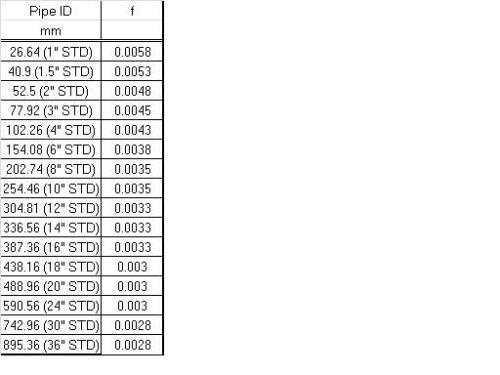
Q BA 2gP 1179d2P121 Where q flow rate per perforation gpm B orifice coefficient assumed as. My experience is that such tests are essential. 900 mm ID with minimum liquid rates in excess of 2 gpmft25 m3hm2.
Two common methods the coefficient of variation and the liquid distribution quality by Moore and Rukovena are implemented for reference. Liquid distributor test for columns. Design of the Liquid Outlet Nozzle and Vortex-Breaker.
900 mm Orifices in base Liquid rates between 2 and 16 gpmft25 40 m3hm2 The Model 126 Intalox distributor and Model 127 redistributor are designed for towers greater than 36 in. Liquid distributor test for columns. In a gravity head distributor this is the sum of the two components.
Siretb Chemical 17 May 10 0236. If higher turndown ratios are required taller risers can be used. In-order to ensure that no gas escape with the liquid phase the following measures were taken.
The unit discharge rate q from each of the perforations is governed by the size of the perforation and the static pressure at its respective location along the pipe. 01-25 gpmft 025-60 m3hm2 n Tower diameter. 35 Cp 00035 NSecSqm Gas Density Calculation.
In determining the settling velocity in a liquid-liquid disper-. Liquid Viscosity. Liquid Distributor Design Calculation.
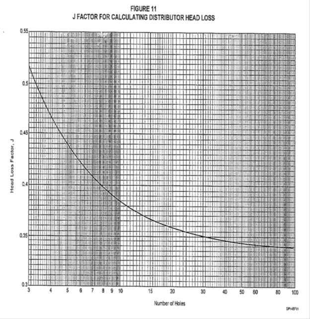
H O is the orifice head in. 1 Sizing the liquid outlet nozzle. And h PD is the distributor head loss on the vapor side in.
PROCESS DESIGN OF GAS VAPOR-LIQUID SEPARATORS PROJECT STANDARDS AND SPECIFICATIONS Page 5 of 45 Rev. Initially set the pipe size of the pipe distributor same as the pipe size feeding the pipe distributor Step 2. UL 05 m3m2h and allow flow rates of about 005-05 1h through each outlet.
Calculate the Reynolds number Rei of the inlet stream to the pipe distributor using the following equation. Beams or on packing with special support grid n Redistribution. 4 Design Philosophy 5 Performance Guarantees 6 Description of Packed Column Internals 7 Design Calculations 8 Liquid Distribution and Redistribution 9 Practical Aspects of Packed Column Design In addition Appendices give examples of design calculations by various methods for both.
The separation process requires three things. Diameters greater than 36 in. Liquid distribution in the packing is estimated in dependence of the liquid distributor design.
This increases the buoyant forces in the Stokes Law equation. Liquid distributor design calculation And below arrives essentially the most awaited killing manicure with long equipment guns all on the nailsWont you love to tease your folks and frighten your enemies with this Resourceful 3d Nail Art Images. Let us straight away get to the steps for sizing a Perforated Pipe Liquid distributor.
The diameter of the droplets is a critical parameter. As the TUMWelChem Cell Model includes liquid distribution characteristics for different types of packing and hydraulic calculations it renders more detailed investigations and optimizations. The bottoms product is almost exclusively liquid while the distillate may be liquid or a vapor or both.
In this section there are tables that assist in making these factored calculations from the various reference sources. Basic Design Concepts Operating Principles of a Coalescer Liquid-Liquid Coalescers are used to accelerate the merging of many droplets to form a lesser number of droplets but with a greater diameter. The scope of the guide is summarized in its clause headings.
In atm x 224141 0234499 CumSec. Liquid distribution in the packing is estimated in dependence of the liquid distributor design. In this work a liquid distributor design method is presented which considers the interaction of the liquid distributor and the packing with the TUMWelChem Cell Model.
3 ft 900 mm n Support features. Unlike a plate column where the gas-liquid contact is stagewise a packed columns gas-liquid contact is continuous. Place determine the selection and design of equipment.
01 April 2011 g Local acceleration due to gravity ms². The structure of liquid distributor should be reasonable to prevent disturbing hold down device for higher mass transfer efficiency. A parameter study with an exemplary column design provides.
Generally path flow liquid on tray is divided into single pass two pass three pass and four pass. Rei 127Qρ. In this design the liquid will flow down the column and pass through the packaging material.
Distillation is a process that separates two or more components into an overhead distillate and bottoms. Necessary components along with distillation calculations. While the liquid flows down the vapor or gas will go up the column in a counter-current manner.
Capillary plates are suitable distributors for very low liquid loads viz. The liquid outlet for this GLS is designed with the objective to prevent any entrainment of the incoming gas with the liquid.
Perforated Pipe Distributor Sizing Calculations Cheresources Com Community
2
2

Distributors Pressure Drop Brewiki

Column Internals Explained Part 2 Separation Technologies
Perforated Pipe Distributor Sizing Calculations Cheresources Com Community

Importance Of Liquid Distributors Part 1 Mach Engineering
Column Internals Explained Part 2 Separation Technologies
0 comments
Post a Comment